
Recently, a student asked me for advice on how to prepare for Kubernetes ClusterChoosing the right network plugin, and what are the implementation principles and differences between different network plugins. To be honest, this question is difficult for me to answer for a while. After all, there are many network plugins in the CNCF ecosystem, such as Calico, Flannel, Cilium, Kube-OVN and so on, which is very confusing.
Even for the same network plug-in, there are multiple networking modes, such as direct routing, bridge, IPIP, VXLAN, eBPF, etc., each of which has its own unique technical characteristics and application scenarios.
In the face of such a complex situation, it is really difficult to make it clear in a few words.
Next I plan to take the Calico network plug-in as an example, through several articles, in-depth analysis of the realization principle of various networking modes, and explore their respective applicable scenarios, and finally combined with the customer's real-life use of scenarios, to explain in detail how to choose the right network plug-in and networking mode.
Kubernetes Networking Basics Review
Before we introduce Calico, let's review the Kubernetes network.The Kubernetes network model consists of the following components:
- IP address assignment: each Pod within the cluster is assigned a unique IP address. Inside the Pod, all containers share the same network namespace, and processes between different containers can communicate via localhost or 127.0.0.1;
- Inter-Pod Communication: Any two Pods in the cluster can communicate with each other, regardless of whether they are on the same node or not, without the need for proxies or address translation (NAT);
- Service and Pod Communication: The cluster provides a unified access portal for back-end Pods through Service. Each Service has a stable IP address, so that even if the back-end Pods change dynamically, the cluster can distribute the traffic to the back-end Pods through the Service IP in accordance with the load balancing policy;
- Pods communicate with the outside of the cluster: the cluster provides advanced route management capabilities through the Gateway API to enable internal cluster services to be exposed to the outside world, making it easy for external services to access cluster resources;
- Network Policy Control: The cluster can use NetworkPolicy to finely control the traffic between Pods and between Pods and external services. By setting access rules, network security is guaranteed and business isolation is realized;
Kubernetes only defines the network model, itself does not implement the container network connection, but through the container network interface CNI to call the network plug-in, the network plug-in to complete the container network connection of the specific configuration and build work.
Calico is an excellent network plugin that not only enables IP address assignment and efficient inter-pod communication for Kubernetes clusters, but also provides powerful network policy features such as network isolation and access control.
In addition, Calico works closely with Kubernetes' Service and Gateway APIs to improve the network performance and security of the entire Kubernetes cluster by building a stable network topology that optimizes communication between Pods and services, as well as between Pods and the outside of the cluster.
Calico Components and Architecture
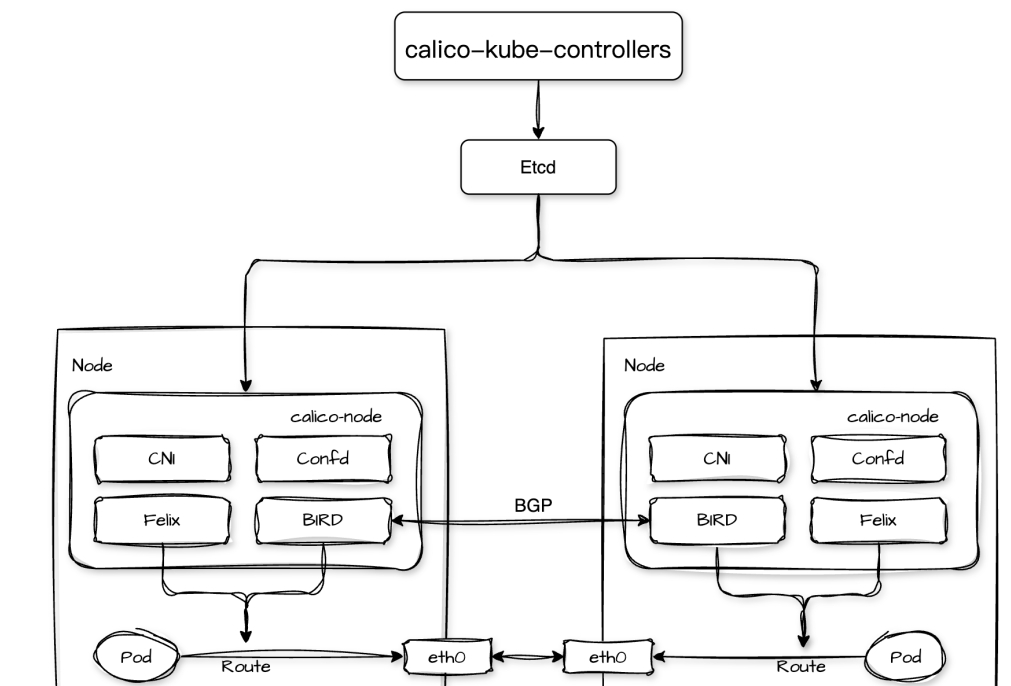
Calico The core components include calico-kube-controllers, calico-node, and etcd:
1. calico-kube-controllers are deployed in Deployment form and are responsible for synchronizing network policies, managing IP pools, monitoring node status, and other important tasks;
2. calico-node runs as a daemon on each node of the Kubernetes cluster and is responsible for performing key tasks such as enforcing Calico's network policy, managing routes, and configuring network interfaces. It consists of multiple processes internally:
- Felix: Responsible for network interface management, route configuration, and access control list (ACL) management on the node, it will monitor network policies and configurations in the cluster from and dynamically configure network interfaces and routing rules on the cluster nodes based on this information;
- BIRD: BGP clients, including bird (for IPv4) and bird6 (for IPv6), BGP clients will obtain routing information from Felix and use Border Gateway Protocol (BGP) to distribute to other nodes in the cluster's BIRD process to exchange routing information, realizing the Pod's cross-node network communication across nodes;
- Confd: Responsible for listening to configuration changes in the cluster, regenerating the relevant configuration file when it detects a configuration update, and notifying processes such as BIRD to reload the configuration;
- CNI: Provides the Calico network for the Kubernetes cluster and configures the network interfaces for containers according to the Calico network configuration during Pod creation and destruction. This includes assigning a unique IP address to each Pod in the cluster, connecting the Pod's network interface to the Calico network, and configuring the appropriate access control rules on the Pod's network interface;
3.etcd: As Calico's storage system, it is responsible for storing Calico's network configuration, policy rules, IP address allocation and other data;
Calico supports a variety of networking methods, including: BGP, IPIP, VXLAN, etc. In this issue, let's start with Calico's most basic BGP mode.
Calico BGP mode
BGP (Border Gateway Protocol) is a TCP-based application-layer decentralized autonomous routing protocol mainly used to exchange routing information between different autonomous systems (AS). Through a TCP connection, BGP routers between different autonomous systems can establish a neighbor relationship.
After a connection is established, the two parties exchange BGP routing information, including information about the reachability of the local network and the paths to other networks.
When a BGP router receives multiple routes to the same destination, it selects the optimal path based on a set of path attributes (e.g., AS path length, next-hop address, local priority, etc.) and policies.
In a Calico network, the nodes of the cluster can act as virtual routers (vRouter) and subsequently propagate the routing information of the Pod network running on the nodes to the entire Calico network through the BGP protocol, so that the Pods in the cluster can achieve efficient and transparent network connectivity through host routing.
Before we dive into the process of forwarding network traffic for Pods in Calico BGP mode, we need to prepare a Kubernetes cluster with the Calico networking plugin installed and BGP mode set to start.
Building a Kubernetes Cluster
There are many tools in the community to build Kubernetes, here I use kebekey, the procedure is as follows:
# installing kubekey $exportKKZONE=cn $curl -sfL https://get-kk.kubesphere.io | VERSION=v3.0.13 sh - # installing Kubernetes cluster and Calico plugin with BGP enabled schema $cat > cluster.yaml <<EOF apiVersion: kubekey.kubesphere.io/v1alpha2 kind: Cluster metadata: name: zlw-cluster spec: hosts: - {name: 10-23- 14-110, address: 10.23.14.110, internalAddress: 10.23.14.110, user: root, sshKey: "~/.ssh/id_rsa"} - {name: 10-23-14-111, address: 10.23.14.111 , internalAddress: 10.23.14.111, user: root, sshKey: "~/.ssh/id_rsa"} - {name: 10-23-14-112, address: 10.23.14.112, internalAddress: 10.23. 14.112, user: root, sshKey: "~/.ssh/id_rsa"} - {name: 10-23-14-113, address: 10.23.14.113, internalAddress: 10.23.14.113, user: root, sshKey: "~/... .ssh/id_rsa"} - {name: 10-23-14-114, address: 10.23.14.114, internalAddress: 10.23.14.114, user: root, sshKey: "~/.ssh/id_rsa"} - {name: 10-23- 14-115, address: 10.23.14.115, internalAddress: 10.23.14.115, user: root, sshKey: "~/.ssh/id_rsa"} roleGroups: etcd: - 10-23-14-110 - 10-23-14- 111 - 10-23-14-112 control-plane: - 10-23-14-110 - 10-23-14-111 - 10-23-14-112 worker: - 10-23-14-113 - 10-23-14-114 - 10-23-14-115 controlPlaneEndpoint: domain: lb.kubesphere.local address: "" port: 6443 kubernetes: version: v1.32.0 clusterName: cluster.local network. plugin: calico kubePodsCIDR: 10.233.0.0/16 kubeServiceCIDR: 10.96.0.0/16 calico: ipipMode: Never vxlanMode: Never bgp: enabled: true asNumber. 64512 peerSelector: all() EOF $kk create cluster -f cluster.yaml -y --debug
In this experiment, I have prepared 6 machines where 10-23-14-110, 10-23-14-111 and 10-23-14-112 are used as master nodes of the cluster and 10-23-14-113, 10-23-14-114, 10-23-14-115 are used as worker nodes.
After the above, we can get a Kubernetes cluster with the Calico network plugin installed. Subsequently, execute the following command on node 10-23-14-110 to check the network status of Calico:
$ kubectl get IPPool default-ipv4-ippool -oyaml apiVersion: crd.projectcalico.org/v1 kind: IPPool metadata: name: default-ipv4-ippool spec. allowedUses: - Workload - Tunnel blockSize: 24 cidr: 10.233.0.0/16 ipipMode: Never natOutgoing:true nodeSelector: all() vxlanMode: Never $ calicoctl node status Calico process is running. IPv4 BGP status +--------------+-------------------+-------+----------+-------------+ | PEER ADDRESS | PEER TYPE | STATE | SINCE | INFO | +--------------+-------------------+-------+----------+-------------+ | 10.23.14.111 | node-to-node mesh | up | 12:31:31 | Established | | 10.23.14.112 | node-to-node mesh | up | 12:31:30 | Established | | 10.23.14.113 | node-to-node mesh | up | 12:31:32 | Established | | 10.23.14.114 | node-to-node mesh | up | 12:31:31 | Established | | 10.23.14.115 | node-to-node mesh | up | 12:31:31 | Established | +------- -------+-------------------+-------+----------+-------------+ IPv6 BGP status No IPv6 peers found.
The Calico Network Plug-in provides both Overlay Network and Underlay Network network scenarios. The Overlay Network implementation includes IPIP and VXLAN modes, while the Underlay Network implementation is in BGP mode.
In the current Calico IPPool configuration, the ipipMode and vxlanMode attributes are both Never, indicating that IPIP and VXLAN modes are not being used, and that BGP mode is being used instead, i.e., Underlay Network is being used.
In addition, we can see that the Calico process on node 10.23.14.110 is running and has established IPv4 BGP connections to five machines from 10.23.14.111 to 10.23.14.115. The PEER TYPE of node-to-node mesh indicates that BGP is using Full Mesh mode. mode, that is, BGP connections have been established between each node in the cluster.
In order to make it clearer how Calico BGP communicates in FullMesh mode, I'm going to start the Pod's communication process from the same node and different node dimensions respectively.
Co-Node Pod Network Communication
First, I deployed two replicas in the cluster and had them both running on node 10-23-14-110:
$ kubectl get pods -owide NAME READY STATUS RESTARTS AGE IP NODE NOMINATED NODE READINESS GATES zlw-01 1/1 Running 0 1h 10.233.133.2 10-23-14-110 zlw-02 1/1 Running 0 1h 10.233.133.3 10-23-14-110 <none
As you can see, the PodIPs for replicas zlw-01 and zlw-02 are 10.233.133.2 and 10.233.133.3, respectively.Next, we execute the following commands to test the connectivity of the network:
$ kubectlexec-it zlw-01 -- ping -c 1 10.233.133.3 PING 10.233.133.3 (10.233.133.3) 56(84) bytes of data. 64 bytes from 10.233.133.3: icmp_seq=1 ttl=63 time=0.149 ms --- 10.233.133.3 ping statistics --- 1 packets transmitted, 1 received, 0% packet loss, time 0ms rtt min/avg/max/mdev = 0.075/ 0.075/0.075/0.000 ms
When accessing the PodIP of zlw-02 in replica zlw-01, we can get a normal response, which means that their network communication is smooth. So what is the forwarding process of traffic between two replicas of the same node?
Container to Host
Let's take a look at copy zlw-01's network equipment:
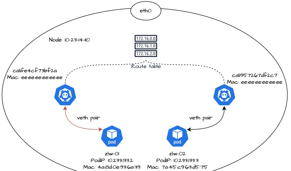
$ kubectlexec-it zlw-01 -- ip a 1: lo: mtu 65536 qdisc noqueue state UNKNOWN group default qlen 1000 link/loopback 00:00:00 :00:00:00 brd 00:00:00:00:00 inet 127.0.0.1/8 scope host lo valid_lft forever preferred_lft forever 2: tunl0@NONE: mtu 1480 qdisc noop state DOWN group default qlen 1000 link/ipip 0.0.0.0 brd 0.0.0.0 3: eth0@if3120: mtu 1500 qdisc noqueue state UP group default qlen 1000 link/ether 4a:8d:0e:93:6a:39 brd ff:ff:ff:ff:ff:ff:ff link-netnsid 0 inet 10.233.133.2/32 scope global eth0 valid_lft forever preferred_lft forever
The command ip a is an abbreviation for ip addr. By looking at its output, we can see that the eth0 NIC address of replica zlw-01 is 10.233.133.2, which is exactly the PodIP address of zlw-01.
The container's eth0 NIC does not appear alone, when creating the container Calico generates a pair of virtual Ethernet cards (veth pair) for the container, one end of which is inside the container, which we see as eth0, and the other end of which is in the node and is usually named with the prefix cali and has an index number. For example, eth0@if3120 means that the eth0 card of the container in replica zlw-01 and the card with index number 3120 in the node are a veth pair.
Next we look at the routing table information for copy zlw-01:
$ kubectlexec-it zlw-01 -- ip r default via 169.254.1.1 dev eth0 169.254.1.1 dev eth0 scope link $ kubectlexec-it zlw-01 -- route -n Kernel IP routing table Destination Gateway Genmask Flags Metric Ref Use Iface 0.0.0.0 169.254.1.1 0.0.0.0 UG 0 0 0 eth0 169.254.1.1 0.0.0.0 255.255.255.255.255 UH 0 0 0 0 eth0
default via 169.254.1.1 dev eth0 is a default route that acts as a tout. The default route is used when the system needs to send packets to a destination address but cannot find an exact match in the routing table.169.254.1.1 dev eth0 scope link belongs to the direct route, which indicates that 169.254.1.1 and eth0 are on the same link, and packets can be transmitted directly on this link without going through other gateways.
In Calico, 169.254.1.1 acts as the default gateway. When packets are generated in the container that are destined for an external address that is not explicitly matched in the routing table (i.e., the destination address is 0.0.0.0), these packets pass through the eth0 NIC in the container, then arrive at the node's cali NIC, and are forwarded to the default gateway 169.254.1.1, which is responsible for subsequent forwarding.
As we know earlier, the replica zlw-01 running on node 10-23-14-110 has a container eth0 NIC that is a veth pair with index number 3120 in the node, so we can execute the following command at 10-23-14-110 to find the corresponding cali NIC:
$ ip a | grep -A 3 3120 3120: calife4cf73bf2a@if3: mtu 1500 qdisc noqueue state UP group default qlen 1000 link/ ether ee:ee:ee:ee:ee:ee brd ff:ff:ff:ff:ff:ff:ff link-netnsid 2 inet6 fe80::ecee:eeff:feee:eeee/64 scope link valid_lft forever preferred_lft preferred_lft forever
From the output, you can see that the specific name of the cali NIC with index 3120 is calife4cf73bf2a. this NIC does not have an IP address, its MAC address is ee:ee:ee:ee:ee:ee:ee.
Next, we can use the tcpdump command to listen for NIC calife4cf73bf2a traffic:
$ tcpdump -i calife4cf73bf2a -ne 03:24:05.122338 4a:8d:0e:93:6a:39 > ee:ee:ee:ee:ee:ee, ethertype ARP (0x0806), length 42: Request who-has 169.254.1.1 tell 10.233.133.2, length 28 03:24:05.122390 ee:ee:ee:ee:ee:ee > 4a:8d:0e:93:6a:39, ethertype ARP (0x0806), length 42: Reply 169.254. 1.1 is-at ee:ee:ee:ee:ee:ee, length 28 03:24:05.122407 ee:ee:ee:ee:ee:ee > 4a:8d:0e:93:6a:39, ethertype ARP (0x0806), length 42: Request who-has 10.233.133.2 tell 10.23.14.110, length 28 03:24:05.122416 4a:8d:0e:93:6a:39 > ee:ee:ee:ee:ee:ee, ethertype ARP (0x0806), length 42: Reply 10.233. 133.2 is-at 4a:8d:0e:93:6a:39, length 28
We can tell from the output of the listening:
1. The eth0 NIC (IP address 10.233.133.2, MAC address 4a:8d:0e:93:6a:39) of replica zlw-01 initiated an ARP request to query the MAC address of 169.254.1.1. The cali NIC calife4cf73bf2a (MAC address ee:ee:ee:ee:ee:ee:ee) of node 10-23-14-110 responded to the request, confirming that 169.254.1.1 has the MAC address ee:ee:ee:ee:ee. (MAC address ee:ee:ee:ee:ee:ee) responded to the request, confirming that the MAC address of 169.254.1.1 is ee:ee:ee:ee:ee;
2. Node 10-23-14-110 initiated an ARP request to the eth0 NIC of replica zlw-01 via the calife4cf73bf2a NIC for the MAC address of 10.233.133.2. The eth0 NIC of replica zlw-01 (MAC address is 4a:8d:0e:93:6a:39) responded to the request, confirming that the MAC address of 10.233.133.2 is 4a:8d:0e:93:6a:39; the
Here we may wonder: why would 169.254.1.1, which is Calico's default gateway, have a MAC address of ee:ee:ee:ee:ee:ee?
In fact, 169.254.1.1 is the default gateway IP that Calico has virtualized for the container network, not the actual physical device IP.
When zlw-01 initiates an ARP request to query the MAC address of the default gateway 169.254.1.1 via the eth0 NIC, the cali NIC calife4cf73bf2a corresponding to eth0 on the node responds to the container's ARP request via proxy ARP and returns its own MAC address, i.e., ee:ee:ee:ee:ee:ee.
Calico uses the cali NIC as a virtual bridge between the container and the node (i.e., the opposite end of the veth pair). Proxy ARP allows the container's traffic to 169.254.1.1 to be encapsulated as a data frame with the destination MAC address ee:ee:ee:ee:ee:ee, which then travels from the container's eth0 NIC to the node's cali NIC, thereby enabling network communication using the node's routing capabilities. The data frame will travel from the container's eth0 NIC to the node's cali NIC, which in turn can use the node's routing and forwarding capabilities to realize network communication.
To verify that the proxy ARP feature is enabled on the cali NIC calife4cf73bf2a on node 10-23-14-110, we can execute the following command on the node
$ cat /proc/sys/net/ipv4/conf/calife4cf73bf2a/proxy_arp 1
A return value of 1 means that the cali NIC calife4cf73bf2a has enabled the proxy ARP function and can answer ARP requests on its behalf.
Next, while we continue to listen for traffic to replica zlw-01 using the tcpdump command, we execute the following command in another new terminal: kubectl exec -it zlw-01 - ping -c 1 10.233.133.3, after which we can see that tcpdump listens for the following results:
10:20:32.661779 4a:8d:0e:93:6a:39 > ee:ee:ee:ee:ee:ee, ethertype IPv4 (0x0800), length 98: 10.233.133.2 > 10.233.133.3: ICMPechorequest, id 12, seq 1, length 64 10:20:32.661882 ee:ee:ee:ee:ee:ee > 4a:8d:0e:93:6a:39, length 64 seq 1, length 64 10:20:32.661882 ee:ee:ee:ee:ee:ee > 4a:8d:0e:93:6a:39, ethertype IPv4 (0x0800), length 98: 10.233.133.3 > 10.233.133.2. ICMPechoreply, id 12, seq 1, length 64
You can see that when replica zlw-01 sends an ICMP request to zlw-02, the traffic is sent from the eth0 NIC in the container, and arrives at the node's cali NIC calife4cf73bf2a via the veth pair, at which time the source IP is 10.233.133.2 (the IP address of replica zlw-01), the destination IP is 10.233. 133.3 (IP address of replica zlw-02), source MAC address is 4a:8d:0e:93:6a:39 (MAC address of eth0 NIC in replica zlw-01), destination MAC address is ee:ee:ee:ee:ee:ee (MAC address of cali NIC calife4cf73bf2a in replica zlw-01), and finally traffic reaches the node. address), and finally the traffic reaches the node.
Next, let's look at how traffic from replica zlw-01 is forwarded from the node to replica zlw-02 on the same node.
Host to Container
Let's look at copy zlw-02 the network equipment first:
$ kubectlexec-it zlw-02 -- ip a 1: lo: mtu 65536 qdisc noqueue state UNKNOWN group default qlen 1000 link/loopback 00:00:00 :00:00:00 brd 00:00:00:00:00 inet 127.0.0.1/8 scope host lo valid_lft forever preferred_lft forever 2: tunl0@NONE: mtu 1480 qdisc noop state DOWN group default qlen 1000 link/ipip 0.0.0.0 brd 0.0.0.0 3: eth0@if3121: mtu 1500 qdisc noqueue state UP group default qlen 1000 link/ether 7a:45:c9:63:d5:75 brd ff:ff:ff:ff:ff:ff:ff link-netnsid 0 inet 10.233.133.3/32 scope global eth0 valid_lft forever preferred_lft forever
We can then find the NIC device with index number 3121 in the node:
ip a | grep -A 3 3121 3121: cali957267df2c7@if3: mtu 1500 qdisc noqueue state UP group default qlen 1000 link/ether ee:ee:ee:ee:ee:ee brd ff:ff:ff:ff:ff:ff link-netnsid 3 inet6 fe80::ecee:eeff:feee:eeee/64 scope link valid_lft forever preferred_lft forever
Therefore, it can be confirmed that the cali NIC cali957267df2c7 on node 10-23-14-110 and the eth0 NIC on replica zlw-02 are a veth pair.
We then look at the routing table for node 10-23-14-110 and see the following:
$ ip route 10.233.133.2 dev calife4cf73bf2a scope link src 10.23.14.110 10.233.133.3 dev cali957267df2c7 scope link src 10.23.14.110
10.233.133.2 and calife4cf73bf2a are the PodIP and cali NIC of replica zlw-01, respectively, while 10.233.133.3 and cali957267df2c7 are the PodIP and cali NIC of replica zlw-02, respectively. scope link specifies that it is a direct route, which means that replicas zlw-01 and zlw-02's cali NICs are on the same node-node link.
When 10.233.133.2 accesses 10.233.133.3, since they are in the same link, packets can be transmitted directly over the Layer 2 link via the MAC address without additional gateway or NAT processing.
Packets destined for 10.233.133.3 are sent from the eth0 NIC of zlw-01, pass through the calife4cf73bf2a NIC on the opposite end and enter the node, and are then forwarded in the node's Layer 2 network to the cali957267df2c7 NIC of zlw-02.
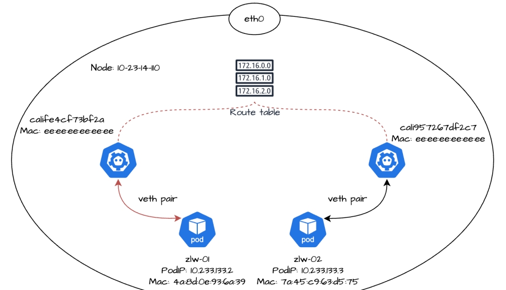
Finally the traffic will reach the eth0 NIC of zlw-02 on the opposite end through the cali957267df2c7 NIC, thus entering the container zlw-02. We can listen to the following data in the eth0 NIC of replica zlw-02:
$ kubectlexec-it zlw-02 -- tcpdump -i eth0 -ne tcpdump: verbose output suppressed, use -v[v].... .forfull protocol decode listening on eth0, link-type EN10MB (Ethernet), snapshot length 262144 bytes 04:29:50.685440 ee:ee:ee:ee:ee:ee > 7a:45:c9 :63:d5:75, ethertype IPv4 (0x0800), length 98: 10.233.133.2 > 10.233.133.3: ICMPechorequest, id 17, seq 1, length 64 04:29:50.685460 7a:45:c9:63:d5 :75 > ee:ee:ee:ee:ee:ee, ethertype IPv4 (0x0800), length 98: 10.233.133.3 > 10.233.133.2: ICMPechoreply, id 17, seq 1, length 64
As you can see, when the traffic enters replica zlw-02, the source IP is 10.233.133.2 (the IP address of replica zlw-01), the destination IP is 10.233.133.3 (the IP address of replica zlw-02), the source MAC address is ee:ee:ee:ee:ee:ee (MAC address of replica zlw-02's cali card), and the destination MAC address is 7a:45:c9:63:d5:75 (MAC address of replica zlw-02's cali card). cali957267df2c7 of replica zlw-02), and the destination MAC address is 7a:45:c9:63:d5:75 (the MAC address of the eth0 NIC in replica zlw-02).
In summary, for network traffic on the same node Pod, the traffic is sent from one copy of the eth0 NIC and arrives at the opposite cali NIC on the node via the veth pair. Since the two cali NICs belong to the same node's virtual link (directly connected to the corresponding container through the veth pair), the data frames will be directly transmitted over the Layer 2 link via the MAC address, and the node's kernel will forward the data frames to the other replica's cali NIC in the Layer 2 network through the point-to-point connection of the virtual link.
The target cali NIC then forwards the data frame to the corresponding container's eth0 NIC through the veth pair, and finally, the response packet is returned through the original route to complete the whole communication process.
After introducing the network communication between Pods on the same node, let's see what are the similarities and differences in the communication process between Pods on different nodes.
Different Nodes Pod Network Communication
Now, we add a new replica named zlw-03 to the cluster and deploy it on a different node from the existing replica zlw-01.
$ kubectl get pods -owide NAME READY STATUS RESTARTS AGE IP NODE NOMINATED NODE READINESS GATES zlw-01 1/1 Running 0 1h 10.233.133.2 10-23-14-110 zlw-02 1/1 Running 0 1h 10.233.133.3 10-23-14-110 zlw-03 1/1 Running 0 1h 10.233.80.0 10-23-14-111
Next, we look at the network devices and routing rules for copy zlw-03:
$ kubectlexec-it zlw-03 -- ip a 1: lo: mtu 65536 qdisc noqueue state UNKNOWN group default qlen 1000 link/loopback 00:00:00 :00:00:00 brd 00:00:00:00:00 inet 127.0.0.1/8 scope host lo valid_lft forever preferred_lft forever 2: tunl0@NONE: mtu 1480 qdisc noop state DOWN group default qlen 1000 link/ipip 0.0.0.0 brd 0.0.0.0 3: eth0@if328463073: mtu 1500 qdisc noqueue state UP group default qlen 1000 link/ether ce:fd:7e:63:4c:ab brd ff:ff:ff:ff:ff:ff:ff link-netnsid 0 inet 10.233.80.0/32 scope global eth0 valid_lft forever preferred_lft forever $ kubectlexec-it zlw-03 -- ip r default via 169.254.1.1 dev eth0 169.254.1.1 dev eth0 scope link $ kubectlexec- it zlw-03 -- route -n Kernel IP routing table Destination Gateway Genmask Flags Metric Ref Use Iface 0.0.0.0 169.254.1.1 0.0.0.0.0 UG 0 0 0 eth0 169.254.1.1 0.0.0.0 255.255.255.255 UH 0 0 0 0 eth0
Subsequently view the cali NIC for replica zlw-03 in node 10-23-14-111:
$ ip a | grep -A 3 328463073 328463073: cali20e9b05e2d6@if3: mtu 1500 qdisc noqueue state UP group default qlen 1000 link/ether ee:ee:ee:ee:ee:ee brd ff:ff:ff:ff:ff:ff:ff link-netnsid 0 inet6 fe80::ecee:eeff:feee:eeee/64 scope link valid_lft forever preferred_lft forever
So we can see that the PodIP of replica zlw-03 is 10.233.80.0 and the MAC address of the eth0 NIC is ce:fd:7e:63:4c:ab. The name of the cali NIC on the veth pair counterpart is cali20e9b05e2d6, and the MAC address is ee:ee:ee:ee:ee:ee.
Container to Host
We initiate a network request at replica zlw-01 to replica zlw-03:
$ kubectlexec-it zlw-01 -- ping -c 1 10.233.80.0 PING 10.233.80.0 (10.233.80.0) 56(84) bytes of data. 64 bytes from 10.233.80.0: icmp_seq=1 ttl=62 time=0.382 ms --- 10.233.80.0 ping statistics --- 1 packets transmitted, 1 received, 0% packet loss, time 0ms rtt min/avg/max/mdev = 0.382/0.382/ 0.382/0.382/ 0.382/0.000 ms
The traffic will be sent from the eth0 NIC of replica zlw-01, pass through the calife4cf73bf2a NIC on the opposite end, and eventually arrive at node 10-23-14-110, a process that is no different from the way we discussed earlier about traffic going from containers to hosts.
Next we focus on how traffic is forwarded between hosts.
Host to Host
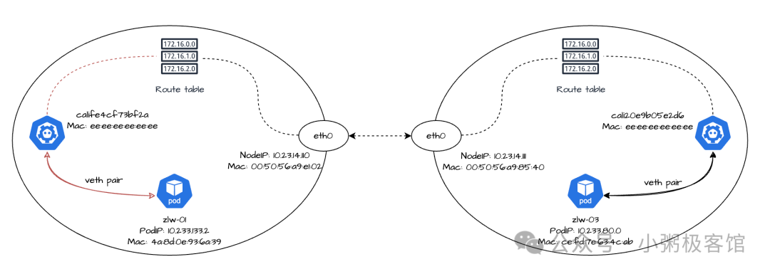
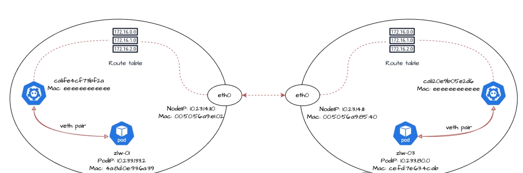
First check the routing rules for node 10-23-14-110:
$ ip route 10.233.133.2 dev calife4cf73bf2a scope link src 10.23.14.110 10.233.133.3 dev cali957267df2c7 scope link src 10.23.14.110 10.233. 80.0/24 via 10.23.14.111 dev eth0 proto bird
A new routing rule has been added to the host compared to the previous one: 10.233.80.0/24 via 10.23.14.111 dev eth0 proto bird. This rule means that for packets whose destination address is within the 10.233.80.0/24 segment, the device will send them via the eth0 interface to the next hop 10.23. 14.111. This route is obtained by the BIRD component of Calico's BGP client.
Next, let's look at the NIC information for node 10-23-14-110eth0:
ip a show eth0 2: eth0: mtu 1500 qdisc mq state UP group default qlen 1000 link/ether 00:50:56:a9:e1:02 brd ff:ff:ff:ff inet 10.23.14.110/24 brd 10.23.14.255 scope global eth0 valid_lft forever preferred_lft forever inet6 fe80:ff:ff:ff :ff:ff:ff inet 10.23.14.110/24 brd 10.23.14.255 scope global eth0 valid_lft forever preferred_lft forever inet6 fe80::250:56ff:fea9:e102/64 scope link valid_lft forever preferred_lft forever
You can see that the MAC address of node 10-23-14-110 is 00:50:56:a9:e1:02.
Next, node 10-23-14-110 will resolve the MAC address of the next hop 10.23.14.111 via ARP protocol. Where 10.23.14.111 is the IP address of node 10-23-14-111eth0 NIC, we can execute the following command on node 10-23-14-111:
ip a show eth0 2: eth0: mtu 1500 qdisc mq state UP group default qlen 1000 link/ether 00:50:56:a9:85:40 brd ff:ff:ff:ff inet 10.23.14.111/24 brd 10.23.14.255 scope global eth0 valid_lft forever preferred_lft forever inet6 fe8080 :ff:ff:ff:ff inet 10.23.14.111/24 brd 10.23.14.255 scope global eth0 valid_lft forever preferred_lft forever inet6 fe80::250:56ff:fea9:8540/64 scope link valid_lft forever preferred_lft forever
You can see that the MAC address of node 10-23-14-111 is 00:50:56:a9:85:40.
After executing the kubectl exec -it zlw-01 - ping -c 1 10.233.80.0 command, we can monitor the following data in node 10-23-14-111 with the tcpdump command:
tcpdump -i eth0 -ne | grep "10.233.80.0" tcpdump: verbose output suppressed, use -v or -vvforfull protocol decode listening on eth0, link-type EN10MB ( Ethernet), capture size 262144 bytes 02:19:54.751970 00:50:56:a9:e1:02 > 00:50:56:a9:85:40, ethertype IPv4 (0x0800), length 98: 10.233.133.2 > 10.233.80.0" tcpdump. 10.233.80.0: ICMPechorequest, id 23, seq 1, length 64 02:19:54.752045 00:50:56:a9:85:40 > 00:50:56:a9:e1:02, ethertype IPv4 (0x0800), length 98. 10.233.80.0 > 10.233.133.2: ICMPechoreply, id 23, seq 1, length 64
As you can see, traffic from replica zlw-01 accessing zlw-03 is sent through node 10-23-14-110 to 10-23-14-111 in the process:
- The source IP is zlw-01's PodIP 10.233.133.2;
- The source MAC address is the MAC address 00:50:56:a9:e1:02 corresponding to the eth0 NIC of node 10-23-14-110;
- The target IP is zlw-03's PodIP 10.233.80.0;
- The target MAC address is the MAC address 00:50:56:a9:85:40 corresponding to the eth0 NIC of node 10-23-14-111;
When the traffic enters node 10-23-14-111, it is then forwarded to replica zlw-03 from the corresponding cali NIC.
Host to Container
Let's look at the routing rules on node 10-23-14-111 for copy zlw-03:
ip r | grep 10.233.80.0 10.233.80.0 dev cali20e9b05e2d6 scope link src 10.23.14.111 blackhole 10.233.80.0/24 proto bird
As you can see, packets destined for the 10.233.80.0 segment will be sent through the device cali20e9b05e2d6, which is replica zlw-03's cali NIC on the node, and subsequent traffic will be routed through this cali NIC to reach replica zlw-03's eth0 NIC, which has recently entered the container. This process is no different from the way we discussed earlier about traffic going from the host to the container.
summarize
After my previous introduction, I believe it is clear that Calico BGP has been used in the Full Mesh modeThe network communication principle of Pods on the same node and different nodes is as follows: each node establishes a peer-to-peer connection through the BGP protocol to realize the exchange of routing information, and then realizes the communication between containers and the host network through the Linux veth pair, and then realizes the forwarding of data packets between nodes through the host routing.
In Full Mesh mode, each node establishes BGP peer-to-peer connections with other nodes, however, the number of BGP connections grows with the number of nodes according to the scale of n*(n-1)/2. This growth will put more pressure on the cluster network when the number of nodes is large, which results in a significant reduction in the efficiency of routing updates.
Therefore, Full Mesh mode is usually more suitable for small and medium-sized clusters with relatively small node sizes, and the official recommendation is to apply it to a node size of 100 nodes or less. If we need to deploy on large-scale clusters, we can choose Route Reflector mode, or deploy in a local deployment scenario by establishing a peer-to-peer connection with a top-of-rack (ToR) router.
In reflector mode, some nodes are set up as route reflectors, and these route reflectors are constructed into a mesh between them, while other nodes only need to establish peer-to-peer connections with some of the route reflectors (usually 2 for redundancy).
This approach reduces the number of BGP peering connections per node significantly compared to Full Mesh mode, so reflector mode is more suitable for large-scale clusters than Full Mesh mode, with the disadvantage that it is also relatively more complex to configure.
That's all for this issue on Calico BGP mode, I will continue to introduce Calico's network communication process in IPIP and VXLAN modes, and how to choose the right network mode for the cluster, we will see you in the next issue!